
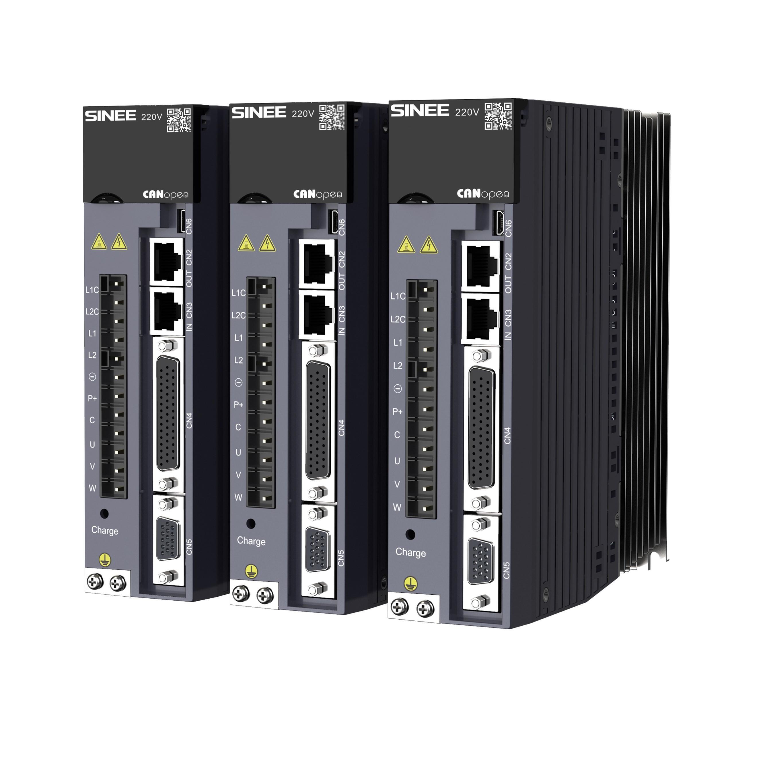
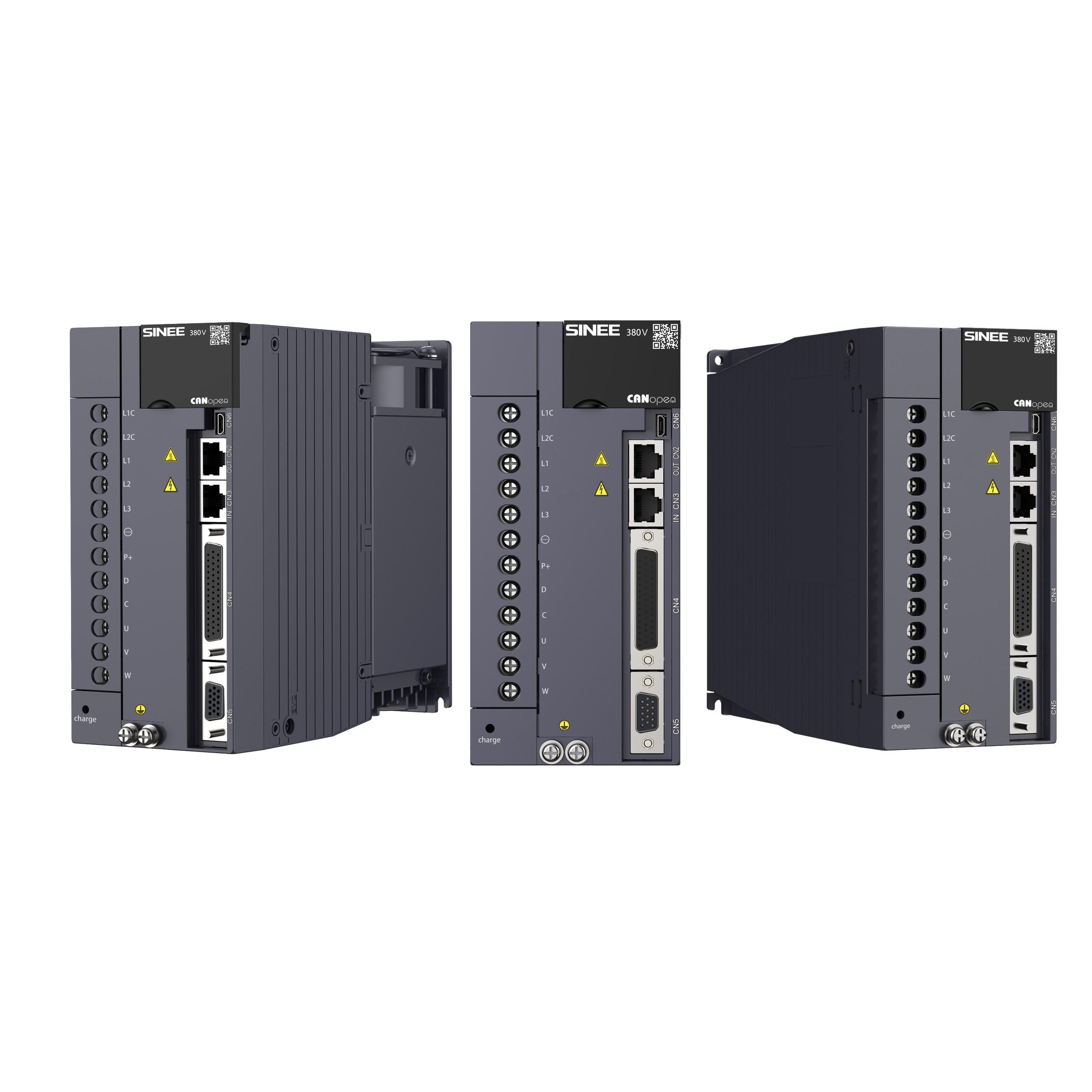
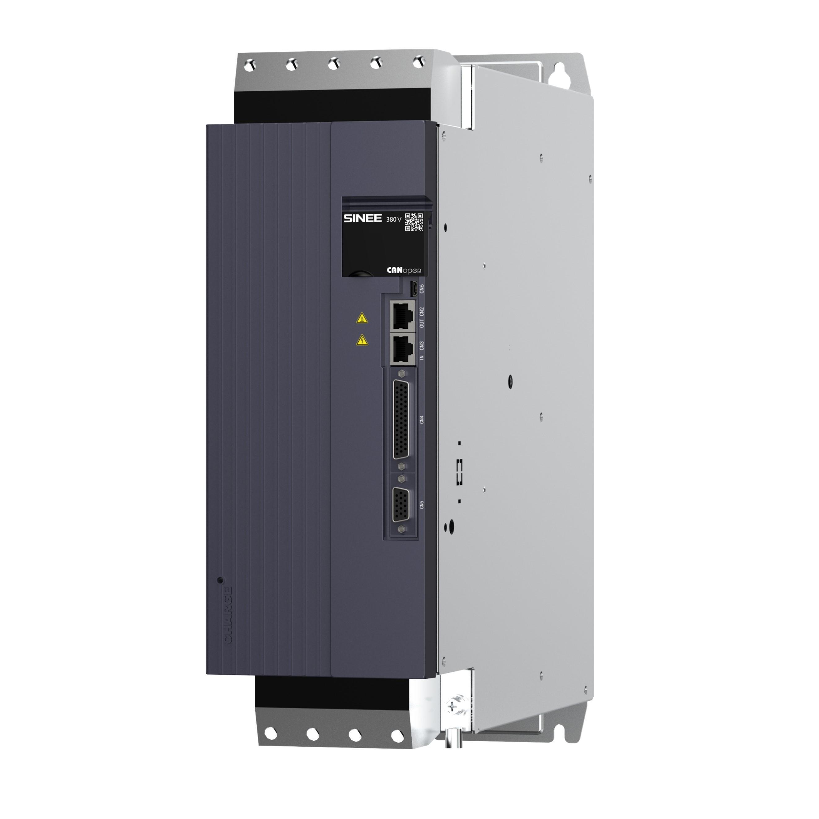
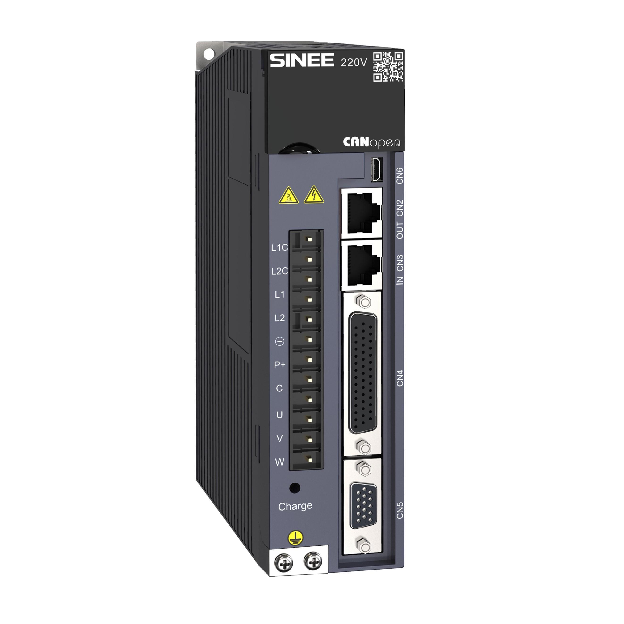
EA180C CANopen network Servo drive
High-speed response performance
•Up to 1.0KHz speed frequency response.
•Shortened positioning time.
•High-speed and high-accuracy real-time synchronous
communication on basis of parallelized system design.

High-accuracy positioning
•Encoder of 17 bit incremental and 23 bit absolute value,
with the powerful control performance, can make the
positioning accuracy less than 5 encoder pulses.

Abandant product series
•Analog & pulse standard type and network type with
EtherCATor CANopen or RS485 protocol supported;
•2500 ppr or serial type with17 bit incremental or 23 bit absolute values encoder available

Small Size
•Size similar to Panasonic A6 series drive, matched with SINEE SES servo motor, can help to minimize the system volume.

Intelligent controls
•Intelligentized resonance suppression
The system has four (4) high-frequency resonance suppression
notch filters, two (2) of them are the FFT-based ones; the others
are manual ones.
Synchronously the vibration suppression filters are provided
to minimize the vibration of long arm machine.
•Control gain switchover functions
The control loop structure on the basis of PDFF may reduce
overshooting efficiently.
The parameter self-adjustment on the basis of inertia
may enhance the site adaptability.

High reliability
•Complete protection function and EMC design
Protection function design on the basis of overall reliability of motor and driver;
EMC design on the basis of graded optimization and system adaptability.
•High-performance motor material and technology ensure the system to run reliably
Containing dysprosium-neodymium-ferroboron magnetic steel, high-strength shaft,
Tamagawa encoder, large-size bearing, encapsulated by resin.

| Item | Specification | ||||
| Input/output signal | Digital input | Modifiable signal distribution | 8-way DI | ||
| Servo enabled, fault resetting, position pulse error counter clearing, speed command direction selection, position/speed multi-stage switch, zero-position fixing enabled, internal command triggering, control mode switch, pulse Inhibited, positive drive Inhibited, Negative driveInhibited, second torque limit, positive inching, negative inching, others | |||||
| Digital output | Modifiable signal frequency dividing | 4-way D0 | |||
| Servo ready, brake output, motor rotary output , zero-speed signal, speed proximity, speed arrival, position proximity, position arrival, torque limit, speed limit, warning output, fault output, others | |||||
| Internal functions | Overrun prevention function | P-OT, N-OT take effect, deceleration stop | |||
| LED display | 5-bit LED display: main circuit CHARGE | ||||
| Protection function | Overvoltage, undervotage, overcurrent, overspeed, IGBT overheat, overload, encoder abnormality, large position error, EEPROM fault, others | ||||
| Others | Two-stage gain switch, automatic gain adjustment, 4 groups of alarm records, JOG operation | ||||
| Communication functions | Communication mode | RS232、RS485、 CANopen | |||
| Synchronizing cycle: 1ms or its integral multiple | |||||
| Supporting the following operation modes: Profile position mode Profile velocity mode Profile torque mode Homing mode | |||||

| Servo drive | Servo motor | ||||
| Drive model | Voltage | Rated output current | Size | Model | Power |
| EA180C-0R9-1B | Single-phase AC 220V | 0.9A | SIZE A | SES04-005-30-2□AY□ | 50W |
| EA180C-1R6-1B | 1.6A | SES04-0R1-30-2□AY□ | 100W | ||
| SES06-0R2-30-2□AY□ | 200W | ||||
| EA180C-2R5-1B | 2.5A | SES06-0R4-30-2□BY□ | 400W | ||
| EA180C-4R8-2B | Three-phase AC 220V | 4.8A | SIZE B | SES08-0R7-30-2□AY□ | 750W |
| SES08-0R7-30-2□BY□ | 750W | ||||
| SES08-1R0-30-2□BY□ | 1000W | ||||
| EA180C-6R2-2B | 6.2A | SER13-1R0-10-2□BY□ | 1000W | ||
| SER13-1R0-20-2□BY□ | 1000W | ||||
| SER13-1R0-30-2□BY□ | 1000W | ||||
| EA180C-011-2B | 11.0A | SER13-1R5-10-2□BY□ | 1500W | ||
| SIZE C | SER13-1R5-20-2□BY□ | 1500W | |||
| SER13-1R5-30-2□BY□ | 1500W | ||||
| EA180C-5R6-3B | Three-phase AC 380V | 5.6A | SER13-1R5-10-3□BY□ | 1500W | |
| SER13-1R5-20-3□BY□ | 1500W | ||||
| SER13-1R5-30-3□BY□ | 1500W | ||||
| EA180C-8R5-3B | 8.5A | SER13-2R0-20-3□BY□ | 2000W | ||
| SER13-2R0-30-3□BY□ | 2000W | ||||
| EA180C-013-3B | 13.0A | SES18-2R9-15-3FBY□ | 2900W | ||
| SER13-3R0-20-3□BY□ | 3000W | ||||
| SER13-3R0-30-3□BY□ | 3000W | ||||
| EA180C-017-3B | 17.0A | SIZE D | SES18-4R4-15-3FBY□ | 4500W | |
| EA180C-022-3B | 22.0A | SES18-5R5-15-3FBY□ | 5600W | ||
| EA180C-028-3B | 28.0A | SES18-7R5-15-3FBY□ | 7500W | ||
| EA180C-038-3B | 38.0A | SIZE E | SEC23-015-15-3FBY□ | 15KW | |
| EA180C-052-3B | 52.0A | SEC23-022-15-3FBY□ | 22KW | ||
| EA180C-062-3B | 62.0A | SEC23-029-15-3FBY□ | 29KW | ||

| ① Product series | ② Motor flange size | ③ Rated output power |
| SER: Standard servo motor SES: High performance servo motor SEM: High-power servo motor | 04: 40mm 06: 60mm 08: 80mm 09: 86mm 11: 110mm 13:130mm 18: 180mm 20: 200mm 26: 266mm | 005: 50W 0R1: 100W 0R2: 200W 0R4: 400W 0R7: 750W 1R0: 1000W 1R5: 1500W 2R0: 2000W 3R0: 3000W 4R4: 4400W 5R5: 5500W 7R5: 7500W 011: 11000W |
| ④ Rated motor speed | ||
| 10: 1000rpm 15: 1500rpm 20: 2000rpm 25: 2500rpm 30: 3000rpm | ||
| ⑦ Inertia type | ||
| ⑤ Voltage level | A: Low inertia B: Medium inertia C: High inertia | |
| 2: 220V 3: 380V | ||
| ⑨ Optional | ||
| ⑥ Encoder type | ⑧ Shaft end | None:No option 1: With brake (DC24V) 2: With oil seal 3: With a brake and oil seal |
| A: 2500ppr incremental B: 17-bit incremental H: 17-bit magnetic incremental F: 23-bit absolute G*1: 2500ppr wire-saving encoder | X: Shaft without keyway*1 Y: Shaft with U-shaped keyway and screw hole*2 Z: Shaft with double round keyways and screw hole | |
| ⑩ Special specifications |
| Item | Description |
| Antirust treatment | Before installation, please wipe off the "rust inhibitor" on the extension of the servo motor shaft before relevant antirust treatment. |
| Notes for encoders | •The shaft extension shall not be impact during installation, otherwise the encoder inside will be cracked.
|
| Pulley installation | •When installing pulleys on a servo motor shaft with a keyway, use screw holes at the shaft end. In order to install the pulley, first insert the double-headed nail into the screw hole of the shaft, use a washer on the surface of the coupling end, and gradually fasten the pulley with a nut. |
| •For servo motor shaft with a keyway, install it with the screw hole at shaft end. For a shaft without keyway, wear coupling or similar methods can be adopted. | |
| •When the pulley is removed, a pulley remover should be used to prevent impact on the bearing. | |
| •In order to ensure safety, a protective cover or similar device shall be installed in the rotating area. | |
 | |
| Centering | •Please use a coupling to connect the device with the machine and keep the axis of the servo motor in a straight line with that of the machinery. The radial runout of the coupling should not be greater than 0.03 mm. If centering is not sufficient, vibration will occur, which may damage bearings, encoders, etc. |
| Installation direction | •Servo motor can be installed in a horizontal or vertical direction. Please do not install the device obliquely, otherwise it may cause wearing of motor bearing. |
| Countermeasures for oil and water | For use in places with water dripping, please confirm the protection rating of the servo motor before use (except the shaft penetration part). For use in places where oil drips to the shaft penetration part, please be sure to use servo motors with oil seals. |
| Service conditions for servo motors with oil seals: | |
| •Please make sure that the oil level is lower than the lip of the oil seal during use. | |
| •Please use the oil seal in a state where the oil spatter can be kept in a good degree. | |
| •When the servo motor is installed vertically upward, please be careful to prevent oil accumulation on the oil seal lip. | |
 | |
| Cable stress condition | Do not bend the cables excessively or apply tension to them, especially for the 0.14 mm2 or 0.2 mm2 core wires of the encoder signal cables, which is very thin. So please do not stretch them too tightly during wiring and use.When installing in the tow chain, high-flexibility tow chain cables must be selected. |
| Connector handling | For the connector part, please pay attention to the following: |
| •When connecting a connector, please make sure that there is no foreign matter such as garbage or metal debris in the connector. | |
| •When connecting the connector to the servo motor, be sure to connect from the side of the main circuit cable of the servo motor first, and the main cable must be reliably grounded. Otherwise, the encoder may fail due to the potential difference with PE. | |
| •When wiring, please make sure the pins are arranged correctly. | |
| •The connector is made of resin. Do not apply impact to the connector, otherwise it may be damaged. | |
| •Always hold the main body of the servo motor during handling while the cables remain connected. Otherwise, the connector may be damaged or the cables may be broken. | |
| •If a cable needs to be bent, due care should be taken during wiring so as not to cause pressure or tension on the connector, otherwise damage or poor contact of the connector may be caused. |


 Address : Floor 5, Building 7, Antuoshan High-tech Industrial Park, Sha'er Community, Shajing Street, Bao'an District, Shenzhen, China
 Tel : 027-87002560
 Fax : 86-0755-86267216
 Email : info@sineedrive.com
Cpyright © 2023 Shenzhen Sinee Electric Co.,Ltd. A certain ICP preparation No. 00000000-0